Introduction
Villa San Marco (Figure 1) is situated on the north-western ridge of the Varano hill in the town of Castellammare di Stabia (NA), where, from the second quarter of the 1st century BCE until the beginning of the 1st century CE, five other villas were built. All these buildings belong to the architectural typology of the otium villas , which allowed the owners to enjoy a privileged and breath-taking view of the Gulf of Naples (Guidobaldi 2018, 436).
The first explorations of the villa, which takes its name from a nearby chapel present there in the 18th century (Bonifacio, Sodo 2001, 31), can be attributed to the excavations of the Bourbon period, ca. 1750-1754. The excavation journals and news about these explorations, as well as drawings of the objects and plans of the structures, were published by M. Ruggiero (1881). After, it was buried in 1762 and it was brought to light again in the 1950s by Libero d’Orsi (1997).
In 1980, the Villa was severely damaged by a massive earthquake in Campania. A major restoration project was carried out by a French-Italian team led by Alix Barbet and Paola Miniero (Barbet 1999, 13).
The restorations allowed the team of scholars to deepen their knowledge on the architectural history of the building and to identify the main construction techniques, as well as a relative chronology of the interventions that modified the original architectural layout.
The Villa and Baths
Architecturally, it is possible to divide the villa into six large sectors having different functions (Bonifacio, Sodo 2001, 32) (Figure 2), for a total extension of about 11.900 m2:
1.an atrium [44], around which a series of rooms developed, including kitchens;
2.a thermal facility, the central focus of which is a large calidarium [29] and a small tetrastyle atrium [25];
3.two large peristyles [1-2; 3-5-20] one of which with a large garden (9), nymphaeum and natatio [15-64];
4.a series of rooms distributed around the peristyle with natatio [3-5-20];
5.a porticoed courtyard 1 situated on the north of the atrium [44] around which various service areas developed, including two latrines and spaces generally identified as servants’ quarters (Ruffo 2009).
6.three recently discovered rooms [83-84-85] located on the south of the perimeter wall of the upper peristyle [1-2] facing a portico with cratic columns [90], still to be fully excavated. 2
Near Villa San Marco, on the north of the so-called ‘strada di breccia’, there is a thermal complex (Figure 3) already explored in the 18th century, but partially uncovered in 2009 as part of a project to reorganise the sea-front entrance to the Villa, which was strongly supported by the Soprintendenza (Ruffo 2010; Saggese forthcoming).
The excavation concerned only the south-western sector of the building, corresponding to a small thermal complex, articulated in the classical succession of apodyterium-frigidarium , tepidarium , calidarium , and a rhodium-type (Ruffo 2010, 224-225, for the hypothesis of a U-shaped portico see Esposito 2012, 151) peristyle-gymnasium (Figure 4). Its eastern arm communicated through openings with a part of the complex still buried but whose planimetric configuration is known thanks to the drawings of Karl Weber (Figure 5), responsible for the graphic documentation of the 18th century excavation campaigns.
Both buildings were entirely decorated with frescoes in the IV style, except for the rooms 39 and 27 of the kitchens of the Villa San Marco, which present pictorial fragments in the III style, evidence of a building phase antecedent to the one covered by the complex at the time of the 79 AD eruption and seem to share the same chronology in the definition of the building interventions. 3
The presence of paintings on almost all the masonry of the buildings, despite the fact that in several cases the state of conservation of the frescoes is not well preserved, concurred to complicate and to partially interpret the construction techniques used to build the wall textures of the two complexes.
The stratigraphic analysis of the walls carried out in the 1980s on the Villa San Marco revealed the use of three different (Rougetet 1999, 44) building techniques:
1. Opus reticulatum ;
2. Opus vittatum: this was used exclusively for the framing of the columns of the atria and peristyles, which were then covered with stucco;
3. Opus mixtum: opus mixtum is, together with opus reticulatum , the most commonly used technique for walling. In his analysis, Jacques Rougetet distinguished three different techniques of opus mixtum , based on the different sizes of the tufa. The first typology, with regularly arranged 9x9 cm tufa tiles, can be seen in the atrium [44] and in the wall [25/22]; the second, with regularly arranged 7x9 cm tufa tiles, was found in the gymnasium [48] and in the wall [35/48]. The third, with regular 9x11 and 12x12 cm tufa tiles associated in verticals with irregularly arranged tufa tiles varying between 10 and 25 cm in width, is found in the masonry that had greater load-bearing capacities, as in the case of the walls of the hall 16 and those of the portico [3-5-20].
In addition to these three techniques, opus craticium was used exclusively in the masonry of the cella hostiaria [82], discovered during the 2008 excavations (Ruffo 2009, 253), in the columns of the portico [90] and in the partitions of the rooms [83-84-85].
In the thermal sector, beyond the ‘strada di breccia’, irregular opus reticulatum with tufa slabs of dimension between 8 and 11 cm is prevalently used for the entrance and the stairwell, while for the thermal rooms a opus mixtum consisting of yellow and grey tufa pillars of around 20x10 cm alternating with irregular reticulation of 8x10 cm (Ruffo 2010, 200).
The survey of buildings
The survey of the building was carried out in three phases, using different and integrated techniques: topographical and architectural survey using laser scanners; photographic and photogrammetric documentation; acquisition of information on possible buried evidence using georadar (Ground Penetrating Radar) surveys. 4
The topographic survey of the complexes was carried out with the aid of a Leica P30 Laser Scanner (Figure 6), a ‘time-of-flight’ laser scanner particularly suitable for the archaeological survey of buildings with complex architecture, which makes it possible to maintain a high quality point cloud in density, precision, and resolution over a range of distances from 0.3 to 120 m thanks to the hybrid technology known as Wave Form Digitizer (WFD), which combines ‘time-of-flight’ technology with the advantages of ‘phase difference’ technology. 5 In order to create an overall point cloud for both monuments, 394 scans had to be made, with an average scan step set at 6.3 mm x 10 m (Saggese 2021, 17). The data was acquired using two different methods. The first, autoresection (Figure 7), applies the topographic principle of forward intersection, which identifies of the position of the gripping station knowing the planimetric disposition of two other points, by measuring the horizontal angles formed by the conjunction of the known points with the directions going to the unknown point (Capra, Dubbini 2009, 83-84). In this specific case, the known points were measured by positioning two targets within a local framing network and subsequently georeferenced with Leica GS18 GPS. The method described allows the pre-registration of point clouds already in the phase of data acquisition and is widely used in the archaeological and engineering fields for outdoor environments and areas. This method was used in most of the environments of Villa San Marco (Saggese 2021, 18). The second method, on the other hand, consists in the free acquisition of the scans without the use of reference targets (Figure 8). In this case, the point clouds are aligned at a later stage, during the data processing phase.
For the photographic and photogrammetric documentation it was decided to use an external support to the laser scanner, although the Leica P30 is equipped with an internal camera with HDR technology with three acquisition steps per shot, 6 in order to obtain a photographic result of higher resolution. These photographs would not be affected by the chromatic distortions caused by the different lighting conditions and relative exposure of the object to be surveyed at the time of data acquisition and which could be calibrated manually in colorimetric terms. For the occasion, a 42 mpx Sony Alpha 7R full-frame mirrorless digital camera was chosen, mounted on a panoramic tripod, Nodal Ninja, which allows the centre of the external camera to be positioned in the same instrumental centre as the laser scanner; the support, which can rotate 360° on the horizontal axis around its pivot, allowed the acquisition of a spherical image that can be perfectly superimposed on the point cloud acquired from each scan. Depending on the focal length used (16 mm) and the size of each single frame (10,000x5,000 px), holding the sensor in a vertical position, sixteen shots in RAW format were taken on the horizontal axis with two different degrees of inclination on the vertical axis (eight shots at +50° and eight shots at -15°) for the composition of the final spherical image. 7
For the mapping of the buried evidence, the georadar instrumentation of the DiSCi Geophysics and Remote Sensing Laboratory was used, i.e. an IDS RIS Hi-Mod 1 georadar equipped with a 600-200 MHz dual frequency antenna. 8
The investigations focused on the ground area on the north-east of the Villa and on the upper peristyle [1-2] with its adjoining viridarium [66]. Regular grids were prepared for both areas as a basis for the measurements acquisition, which were then topographically surveyed with a total station.
Data processing
In the post-production phase, the point clouds acquired with the P30 Laser Scanner were first recorded using the Leica Cyclone 9.1.4 software, which uses a ‘Cloud-to-Cloud’ recognition algorithm. For the alignment of the scans, the folders containing the point cloud files were inserted into the software, which were sorted on a daily basis and subdivided into subfolders by type (scans and photos) and day of acquisition. Following this operation, the scans acquired in the field were manually aligned in free mode. 9
Leica Cyclone 9.1.4 handles this operation in two different ways. The first exploits the potential of the ‘Cloud-to-Cloud’ algorithm, which allows point clouds to be aligned by having the software recognise homologous points—mostly geometries—between them, giving them manual docking constraints. In general, for the recognition to be successful, at least three points should be constrained, preferably on the three x-y-z axes and well distributed in space.
The second involves a manual point-clouds visual alignment, known as ‘visual alignment’ . In this case the two point-clouds to be bound are displayed in false red and blue colours in the plan and in the elevation perspective. In this case the anchoring operation is carried out by roto-translating one of the two clouds over the other, so that they are perfectly superimposed. Once the alignment of the scans was completed, the overall cloud was recorded by applying the ICP algorithm, 10 where the errors were evaluated both on the individual pairs of scans and on the entire group. For a correct registration, the error for Cloud-to-Cloud constraints must be less than the nominal instrumental error, which for this topographic instrument is 0.009 m. and therefore must be below 0.027 m. on the overall group error. 11
The evaluation of the errors on a single pair of scans and on the whole group was below the values shown here (Figure 9).
The photographic images, in RAW format, useful for colouring the point cloud and extracting detailed orthophotos of every single vertical surface, were optimised using the Adobe Photoshop CameraRaw software, from which an initial Digital Negative (*.dng) file was extracted. Subsequently, the file was imported into the ColorChecker Passport software (Figure 10), where profiles (*.dcp) were created, useful for applying, during the colorimetric retouching, the exact profile of the light captured by the camera at the moment of the shot. This retouching is applied to RAW files within Adobe Photoshop CameraRaw and consists in the white balance by controlling the exposure through the colorimetric parameters defined by the profiles extracted by the color-checker (Figure 11). The parameters that were changed according to the information from the profiles are exposure, light, contrast, shadows, whites and blacks, leaving temperature and hue unchanged. After this procedure, the individual shots were entered into the PTGui software, 12 where it was possible to compose the spherical images perfectly superimposed on the scans. After this procedure, the produced panoramas were named with the same name as the scan they were associated with and were imported into Cyclone 9.1.4 software to colour the point clouds. Each scan was exported to a file (*.e57), which contained the textured point cloud and the RGB value information referring to the associated spherical images. For the creation of the orthophotos of all vertical surfaces, the files (.*e57) extracted by Cyclone were imported into Cyclone 3DR 19.1 software. This software allows the creation of high resolution meshes and the translation of the information present in the files (*.e57), recomposing the spherical images, for their texturing (Figure12). 13
Achievements and preliminary considerations
The work carried out at Villa San Marco by the team from the University of Bologna is part of an important project for the rehabilitation of the ancient monuments of Stabiae promoted by the Archaeological Park of Pompeii and involving several Italian and foreign 14 university institutes, using a protocol similar to the one already tested in the ‘Piano della Conoscenza’ of the Great Pompeii Project (Fichera et al. 2015; Giorgi, Sassatelli 2017). The aim was to carry out a topographical survey almost forty years after the last systematic study carried out on the monument, which laid the foundations for the chronological serialisation of the Villa’s development phases, as well as its architectural study (Barbet and Miniero 1999). The data elaborated will be analysed and studied in order to further deepen the understanding on the architectural history of the building and to be compared with the previous research. 15
However, this is complicated by the fact that the analysis of the stratigraphies of the walls of the building appears difficult due to the various events that have affected the Villa San Marco monument since its rediscovery in 1749: for instance, the extensive and invasive restoration work carried out by d’Orsi from 1951 onwards, a time when the precarious static condition of the ancient masonry, heavily damaged by the destructive power of the pumice and lapilli produced by eruption of Vesuvius in 79 AD was perceived; the countless breaches opened in the masonry by the Bourbon excavators; the overall reconstruction that the monument underwent due to the significant damage caused by the earthquake that struck Campania in 1980.
The first result produced by this work was the elaboration of a georeferenced and updated plan of the two buildings in a CAD environment. This was produced by drawing directly on the point cloud in the Autodesk AutoCad Map 3D software using the Cyclone CloudWorx application tool. This tool allows the overall point cloud to be viewed within the CAD environment by calling it up from the project’s Model Space within Cyclone. It was created on a scale of 1:1 adopting the graphic standards of the Great Pompeii Project ‘Piano della Conoscenza’ protocol, for a final restitution on a scale of 1:50 (Figure 13).
The orthophotos of the elevations of all the vertical surfaces of the buildings were returned in scale 1:20 with extension *.jpg/*.tiff (Figure 14). These drawings are very useful for the analysis of the walls and necessary for the mapping of the deterioration, as well as for a general survey of the state of conservation of the monument and for the planning of possible restoration works.
As far as the survey aspect is concerned, the method of acquiring photographic and photogrammetric documentation is innovative, especially in terms of performance, since with the use of the Nodal Ninja support, it was possible to acquire a single datum useful both for the colouring of the point cloud and for the production of high-resolution orthophotos of the vertical surfaces without having to carry out a photogrammetric survey dedicated to each wall.
From an archaeological point of view, the new survey enabled us to document in detail all the surfaces of the villa, from which it is possible to restore the monuments to their original appearance.
From an initial analysis of the three-dimensional model produced, some sectors of the Villa, such as the thermal complex and the new rooms brought to light in 2008 and 2009, in which the restoration interventions appear less invasive, reveal various minor interventions that allow us to understand how the building often underwent renovations and adaptations of the spaces and furnishings according to the different needs of the owners or its own use.
It is therefore possible to state that the historical evolution of the monument is very complex and, although the chronology established by the Italo-French team is correct and acceptable, some gaps still remain unresolved and, in most cases, they can be contextualised during the transition between the Claudian-Neronian period and the last phase of use before the pyroclastic layers of Vesuvius marked the abandonment of the building.
Here, therefore, it is suggested that the terminology associated with the chronologies of the monument need to be revised, where the term ‘phase’, by which it is meant the moment of planimetric modifications of the building with a consequent change of use of the entire neighbourhoods, could be replaced by the term ‘period’; instead, minor interventions may be associated with the term ‘phase’, and thus framing ‘phases’ within ‘periods’.
Bibliography
- Barbet, A. 1999. ‘Introduzione’, in La Villa di San Marco a Stabia , edited by A. Barbet, and P. Miniero, 13-14. Collection du Centre Jean Berard. 18. Roma: L’Erma di Bretschneider.
- Barbet, A. and P. Miniero. Eds. 1999. La Villa di San Marco a Stabia . Collection du Centre Jean Berard. 18 Roma: L’Erma di Bretschneider.
- Bonifacio, G., and A.M. Sodo. 2001. Stabiae: guida archeologica alle ville . Castellammare di Stabia: Nicola Longobardi Editore.
- Boschi, F. 2020. Archeologia senza scavo. Geofisica e indagini non invasive . Bologna: Bononia University Press.
- Capra, A., and M. Dubbini. 2009. ‘Rilievo topografico per l’archeologia’. In Groma 2. In profondità senza scavare , edited by E. Giorgi, 69-90. Bologna: BraDypUS.
- d’Orsi, L. 1997. Gli scavi di Stabiae (1950-1968). Giornale di Scavo . Roma: Quasar Edizioni.
- Esposito, D. 2012. ‘Su un possibile praedium imperiale a Stabiae ’, in Oebalus. Studi sulla Campania antica 6: 143-163.
- Fichera, M.G., L. Malnati, and M.L. Mancinelli. 2015. ‘Grande Progetto Pompei: la Direzione Generale per le Antichità e il Piano della Conoscenza’. In Archeologia e calcolatori. Supplemento 7 : 25-31.
- Franzini, M., V. Casella, and A.M. Manzino. 2021. ‘Allineamento di nuvole dense di punti con ICP pesato tramite segmentazione basata su eigenfeature’, in Asita Academy : 205-220.
- Giorgi, E. and G. Sassatelli. 2017. Pompei Intra-Extra. Archaeologists from the University of Bologna in Pompei . Bologna: Bononia University Press.
- Goodman, D. 2009. ‘GPR methods for archaeology’, in Seeing the unseen. Geophysics and Landscape archaeology , edited by S. Campana, and S. Piro, 229-244. London: CRC Press.
- Guidobaldi, M.P. 2018. ‘Stabia ’ , in Pompei, Oplontis, Ercolano, Stabiae. Guide archeologiche Laterza , edited by F. Pesando, and M.P. Guidobaldi, 434-471. Roma-Bari: Laterza Editore.
- Rescigno, C. and M. Silani. Forthcoming. ‘Nuovi dati dai portici di Narcisso’ in Stabiae. Ricerche, progetti, prospettive. Atti del Convegno , edited by C. Rescigno.
- Rougetet, J. 1999. ‘Construction et architecture’, in La Villa di San Marco a Stabia , edited by A. Barbet, and P. Miniero, 41-58. Collection du Centre Jean Berard. 18. Roma: L’Erma di Bretschneider.
- Ruffo, F. 2009. ‘Sulla Topografia dell’antica Stabiae . Osservazioni sulla Villa San Marco e sul cosiddetto impianto urbano alla luce delle recenti indagini archeologiche. (2008-2009)’. Oebalus. Studi sulla Campania in Antichità , 4: 235-271.
- Ruffo, F. 2010. ‘L’insula sud-occidentale del cosiddetto ‘impianto urbano’ di Stabiae. Nuovi dati dalla recente campagna di scavo (2009)’. Oebalus. Studi sulla Campania in Antichità , 5: 177-238.
- Ruggiero, M. 1881. Degli scavi di Stabia dal MDCCXLIX al MDCCLXXXII. Napoli: Tipografia dell’Accademia Reale e delle Scienze.
- Saggese, Dario 2021. ‘Documentare i monumenti in archeologia: il caso di Villa San Marco a Castellammare di Stabia (Na)’, in Spring Archaeology. Atti del Convegno, Siena 15-17 maggio 2020 , edited by A. Bellotti, L. Luppino, M. Messineo, and M. Scarcella, 15-31. Oxford: Archaeopress.
- Saggese, D. forthcmonig. ‘Il complesso delle terme di Villa San Marco: ricerche in corso’ in Stabiae. Ricerche, progetti, prospettive . Atti del Convegno , edited by C. Rescigno.
- Terpstra, T. 2013. ‘Preliminary Field Report on the 2012 Excavations at the Villa San Marco, Stabiae ’, in Fasti OnLine Documents & Researches , 286: 1-7.
- Terpstra, T., and F. Del Vecchio. 2017. ‘Preliminary Field Report of the 2014 Excavations and Ceramics in Villa San Marco, Stabiae ’, in Fasti OnLine Documents & Researches , 381: 1-14.
- Terpstra, T., L. Toniolo, and P. Gardelli. 2011. ‘Campagna di scavo APAHA 2011 a Villa San Marco, Stabiae: relazione preliminare sull’indagine archeologica’, in Rivista di Studi Pompeiani , 22: 199-205.
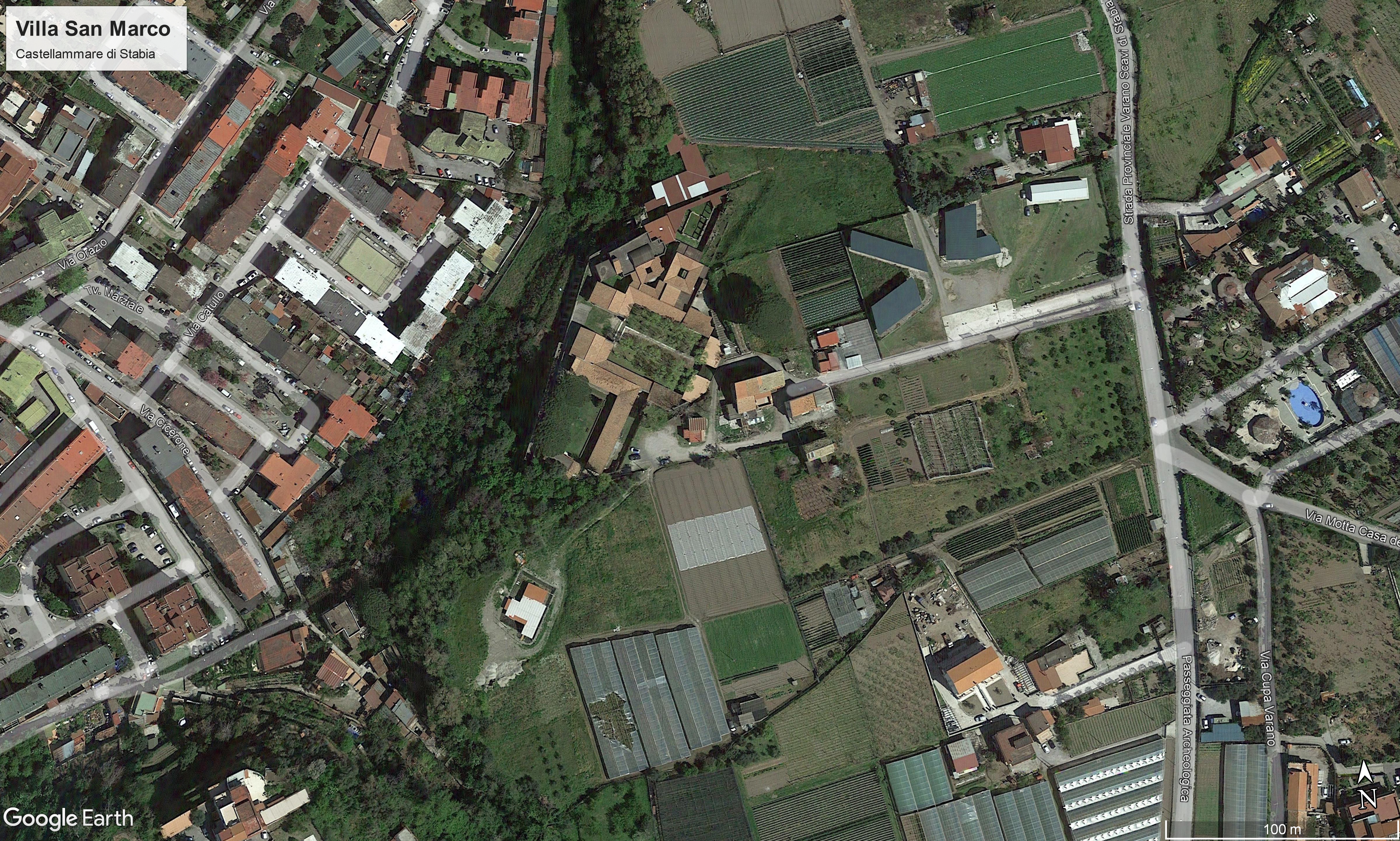 Figure 1. Castellammare di Stabia, Villa San Marco. Aerial view of the ancient complexes (from Google Earth)
 Figure 2. Castellammare di Stabia, Villa San Marco. Arrangement of the rooms (Guidobaldi 2018, 450).
 Figure 3. Castellammare di Stabia. The thermal complex (author’s elaboration).
 Figure 4. Castellammare di Stabia, thermal complex. View from the south corner of the peristyle-gymnasium (from Esposito 2012, 150).
 Figure 5. Stabiae. Excerpt from Karl Weber’s plan. In red the building investigated in the 18th century (author’s re-elaboration from Ruggiero 1881, Tav. I, 184).
 Figure 6. Csatellammare di Stabia. Villa San Marco. Leica P30 laser scanner being acquired (photo by the author).
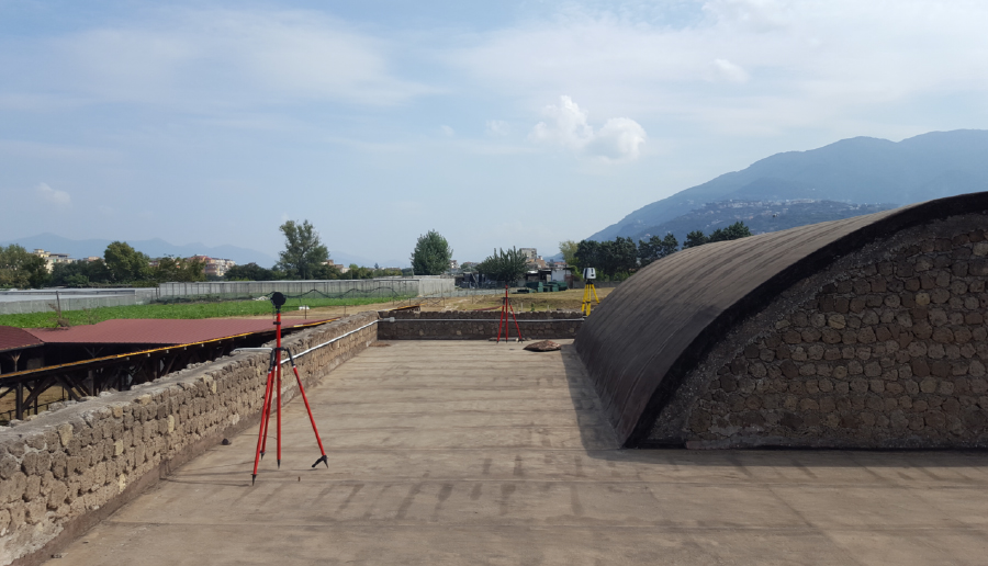 Figure 7. Castellammare di Stabia, Villa San Marco. Data acquisition in autoresection mode (photo by the author).
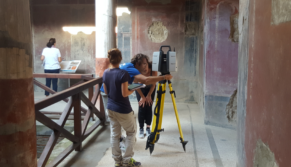 Figure 8. Castellammare di Stabia, Villa San Marco. Data acquisition in free mode (photo by the Alessandro Mauro).
 Figure 9. Error assessment after point cloud recording (author’s elaboration)
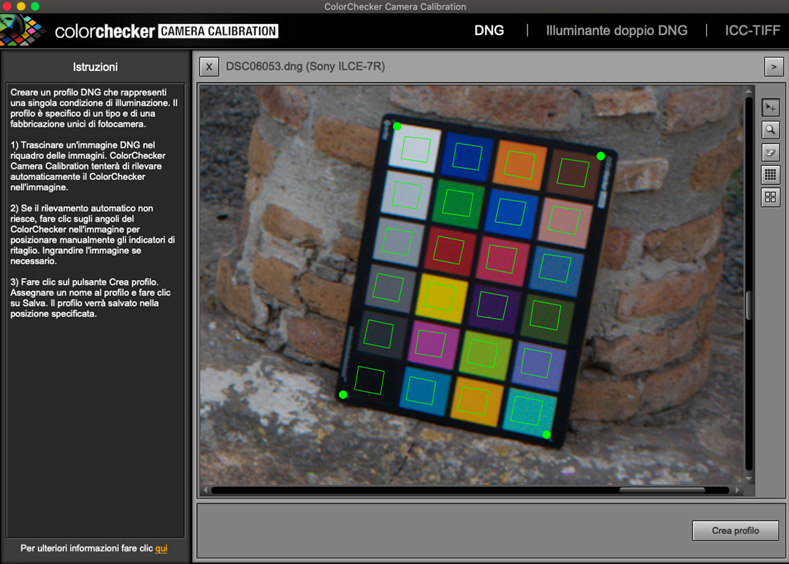 Figure 10. Creation of profiles within ColorChecker Passport (author’s elaboration).
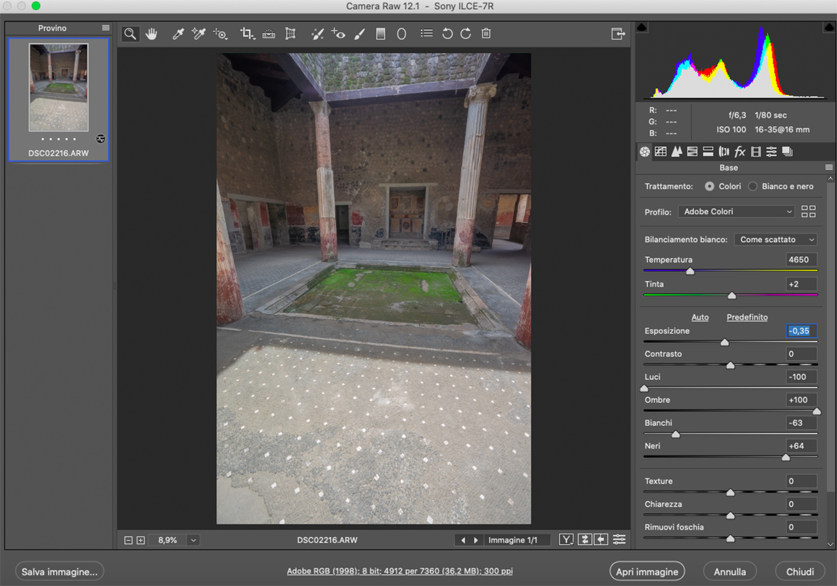 Figure 11. Calibration of spherical images in Adobe Photoshop CameraRaw (author’s elaboration)
 Figure 12. Recomposition of the spherical image in Cyclone 3DR.
 Figure 13. Castellammare di Stabia, Varano plateau. Planimetric restitution of Villa San Marco from laser scanner survey 2018; scale 1.50 (author’s elaboration).
 Figure 14. Villa San Marco. Orthophoto of the elevation of the room 25 (author’s elaboration).